The
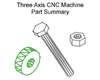
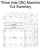
attached PDF (CNC-Part-Summary.pdf) provides detailed cost and sourcing
information for each and every required part. Listed here is only a
summary
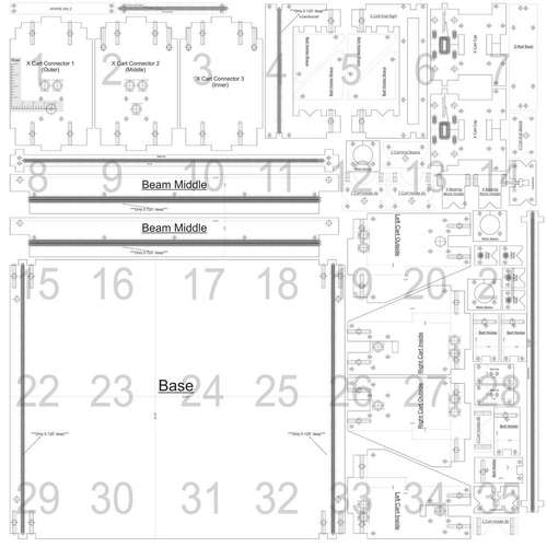
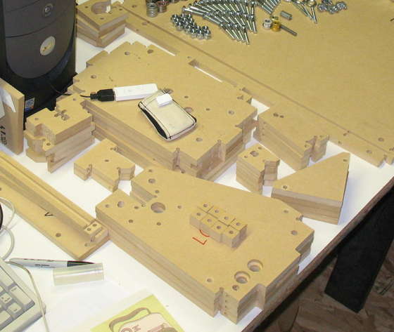
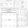
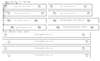
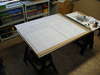
Sheet Stock --- $20
-a 48" x 48" piece of 1/2" thick
MDF (any 1/2" sheet stock can be used I have plans to make my next
version out of UHMW but cost was prohibitive this time around)
-a 5"x5" piece of 3/4" thick MDF (this is used to make spacers so any piece of 3/4" stock found around the shop could be used)
Motors and Controllers ---- $255
-An
entire instructable could be written on chosing a controller and
motors. In short what is required is a controller capable of three axes
of control (with pulsed step and direction inputs) and motors with
about 100 oz/in holding torque. I sourced mine from
http://hobbycnc.com they have worked well and the kit was quite easy to solder. (
direct link )
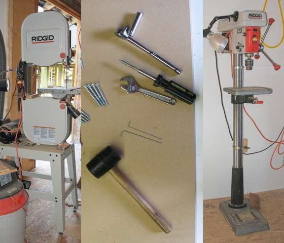
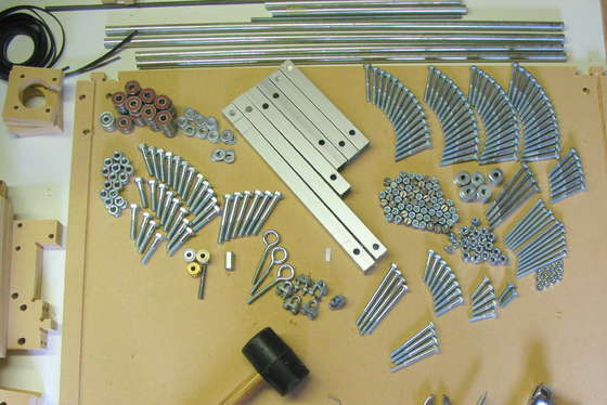
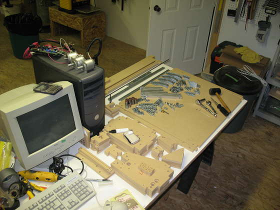
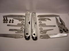
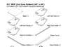
Hardware--- $275
-These
parts can be acquired from three places. The conventional items can be
acquired at Home Depot, the specialty drive products are easy to find
at any industrial supplier, I used McMaster Carr
(http://www.mcmaster.com) (I chose them because they have a nice online
store), and finally because of the large number of bearings required I
found the best price from an online seller (http://vxb.com) which sells
100 for $40 (leaves quite a few left over for other projects) (
direct link )
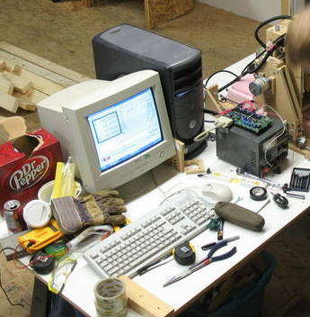
Software --- (free)
-What
is required is a program to draw your designs (I use CorelDraw), and a
programme capable of interpreting these files into pulses to be sent to
your controller. I'm currently using a trial version of Mach3 (
http://www.machsupport.com )but have plans to convert to LinuxCNC (An open source machine controller which uses linux) (
http://www.linuxcnc.org )
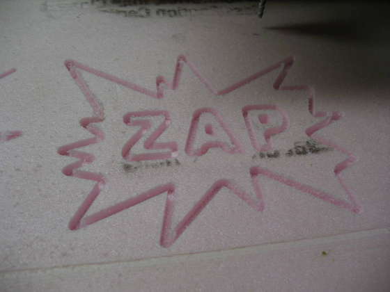
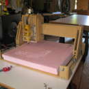
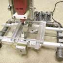
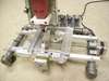
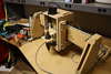
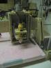
Router Head--- (extra)
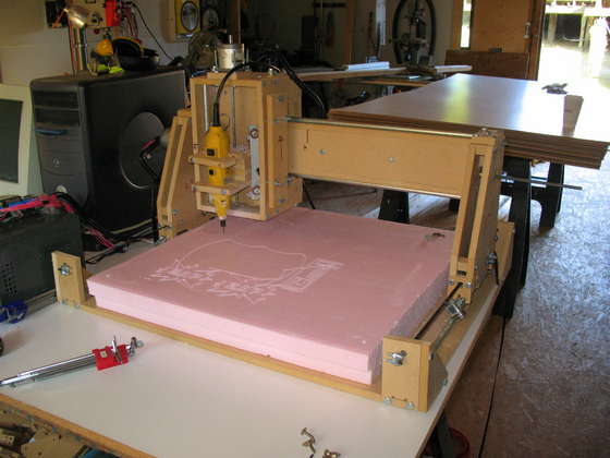
-I attached a dremel type cutting tool to my machine however if you are more interested in additive construction (like
fab@home or
RepRap) you may wish to look into their deposition tools.
Details
-the
metric components and especially the cross nuts aren't very popular and
I had to visit several Home Depots in my area before I had enough.
-I
couldn't find a way to link to parts directly on the MCMaster Carr
site. To find them go to www.mcmaster.com and search for the part #


 CNC (guide)
by
noahw
CNC (guide)
by
noahw


 DXF-05-MDF-SimpleDXF.dxf988 KB
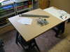


 3 Axis CNC Router - 60"x60"x5" - JunkBot
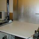 Make a CNC Hot Wire Foam Cutter from parts available at your local hardware store
 Open Manufacturing - (How to Build 30 (SERB) Kits)
 Homebrew Laser Cutter made by Zach Radding
 Dremel Carver/Duplicator like a Human Powered CNC Router
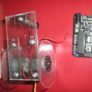 DIY prototypes (robots or art design), with homemade pieces (recycling guide) Part One


Also the paper dimensions are showing in acrobat is 8x10?
What it boils down to: 122 cm = 4 feet. 244 cm is 8 feet. MDF is always delivered in imperial units....
please can I have the all dimensions for the base .
I have built my own CNC mill capable of milling in softer metal alloys a few years ago. Using is and keeping it running takes up a lot of time but is also great fun.
I've made everything but the stepper motors and Win32 software myself. Hardware platform, electronics, PCB and micro-controller firmware. You can check out the build at my website: www.volunteerlabrat.com/cnc.html
Should you choose to make your own CNC mill then go for it. It's so much fun!
Cheers! David
i got evething today but the motor and motherboard
i spent from 7 am to just know 12:13 am lineing up the sheet's of paper
and cuting the wood out
for thow's that have not started get the layout printed at staple's ask for a 48"x48" well take a week to get it they well hafe to ship it well cost you 23$
don't get it as a blueprint it will have line's in it that well mess you up on your cut's
if not have fun it well take you a good bit and a fest in the wall
2ed don't do what i did i used a jegsaw couse my roter router wen't up
i new i would not have a good cut from the start but i got a really good cut for it being a jegsaw bad timeing for my roter router grrrr
as for that i got everthing cut ill put it togather tomorew wonce i get my motor's and all i thank ill just have my cnc cut me new board's thin replace it
thank's again out of every cnc i seen your's or the best and very easy to understand i feel like im building a $5.000 cnc here i thot it was going to be small but hmmm biger thin i thot i did exstend the bass thow
couse after im done im going to exstend everthing
p.s i am haveing fun with this project and it's not something that well take you one day so im really likeing this
got something to ask you thow not for me couse well i done gone throw this
and sorry for the spelling here
i taken the meserment's to homedepo for the nut's and bolt's and well had a problem 0.25 is 1/4 in i not used to this meserment i felt like a noob walking into homedepo into i had 5 home depo worker's working on this with me lol is there a way you can post a txt or something for the next someone i allready got it figered out not hard to learn just did not know it
this my farst time even trying to build or run a cnc i built halfpipe's and music studio's so this won't be a problem
thank you for this by the way i spent 2 munth's studioing cnc programs'
and looking for digram's and help out of all of thim i got every info off your page and even understand it better your's is allso the best i seen on here
i well take a pic of it after done for you
How to control the z-axis, if laser cutter is used (ON/OFF)?
Awaiting replies...//MEROG
if you can email me at nicholasfischer@rogers.com i would really apprecoate it
Once this is made, what are the practical purposes?
Can It make a copy of itself?
How do I tell it what to do?
Is that a normal drill or something specific?
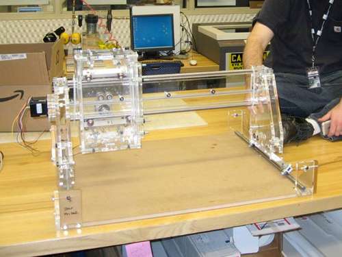
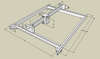
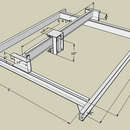
I want to provide a 3D model of this machine that I made in Google Sketchup for everyone to use to help learn more about how this machine fits together. I've checked with the author, and he's fine with me providing it to the community. I wish I had something like the model when I was first assembling the machine; it took a lot of trial-and-error to figure it all out. Hopefully this model will make the road easier for future CNC'ers.
I made this model because I plan to expand the Y-axis to 36", so now I have a virtual copy of my machine to modify. Enjoy!
http://sketchup.google.com/3dwarehouse/details?mid=23e1c5366b479dca8963c446242873ee
Just what I was hoping for... I wanted the original version...
Thanks a lot for sharing this!!
-Wayne Rodrigues.
Not its not. You just got to add some things to it.
Waddya want to export the file as? STL? DXF? OBJ? .X? Find the ruby script you want, download and install it .
By the way, Google Sketchup (free version) can also export COLLADA files (.dae or Digital Asset Exchange), which can be imported into a variety of other programs...
To the rest of you: now you've got an easy way to convert the sketchup model to whatever format your heart desires. Enjoy!
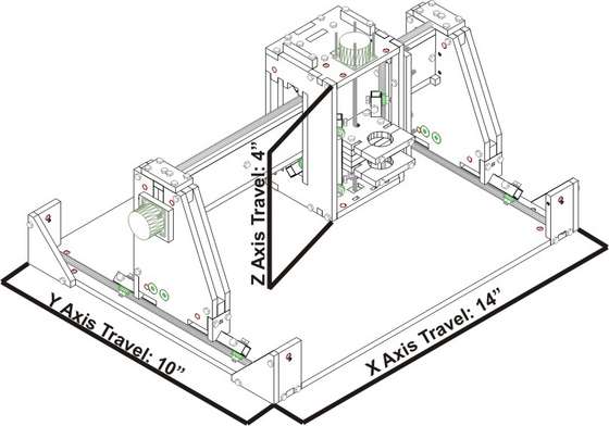
When you say X Axis Travel, you mean the distance the Dremel travels along the X axis?
Or do you mean that is the horizontal part of the base?
I guess it might be the first one right?
-Wayne Rodrigues.
Please......
-Wayne Rodrigues.
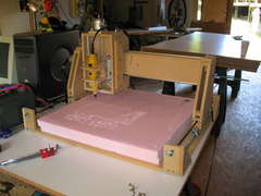
The footprint of this machine is 31 inches on the X Axis, 25 inches on the Y axis. The X Axis travel is about 14.5 inches, and the Y Axis travel is about 10 inches.
You can learn more about the dimensions if you download my Sketchup 3D model of this machine, which I posted down below.
The Best way to Run this Machine is to use a free version of MACH 3 software up to 500 lines of gcode. available form Artsofts website of you can buy it at www.makecnc.com
use it with a driver board that uses step and direction signals
these are available for under $200 also at the URL above if you like.
you will need somthing like a 24 volt 6.5 amp power supply to run the driver board available on ebay just search under 24 volt CNC power supply. about $30 bucks
also paralell cable ,also available on ebay just search for CNC cable about $4
4 wire securty wire for hook up from home depot.
you can use small nema 23 steppers available plenty of places and at www.makecnc.com
if you get the whole package from makecnc.com you get a configuration file to set the whole thing up turn key so you dont have to worry abouit trying to figure out the number of turns a screw will move the dremel and the belts etc etc. and port and pin setups
Just thought i would let you all know somthing about the electronics side of this project as somone asked about ports and pins
Please... this would help me heaps as I don't have access to Letter Page Sizes (incase you don't know the size you have given for is for "Letter")
By the way, it will make a difference if I use A4 and Letter right? Coz this is designed for Letter and if I use A4 it won't be right.....
I am researching the CNC market, and cannot decide whether to start small, or start with the one I want...
What software, controllers, etc did you use?
Thanks,
Doug
skibum2b@yahoo.com
Also what would it take to get this to mill nonferrous metals?
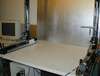
I layed down the masking tape, then sprayed the 77 on both the tape and back of the paper.. it dried in a few minutes and worked very well.. stayed on well for the cut process, and
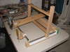
I had to go back and make some different motor spacers (to fit my motors) and just glued it to the mdf.. and wow I'm really glad I did that.
Would you sell a complete unit? If yes how much including delivery to Australia SYDNEY
Thanks in advance
JC
but you will soon be able to get the FAB files( Gcode and instructions)
from my website www.makecnc.com
to be able to have one cut out for you no matter where in the world you are
about two weeks and they will be available
But first: I'll make the acrylic version on my school's Epilog :P
please, could you help me and tell me the metric measure ?
Oscar
for that is no converter!
#8 means number eight Nuts, I would suggest you get them from where he gets them or some where equivlient